

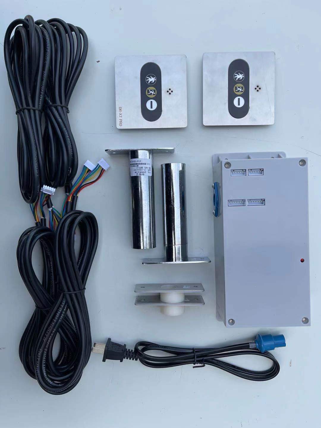
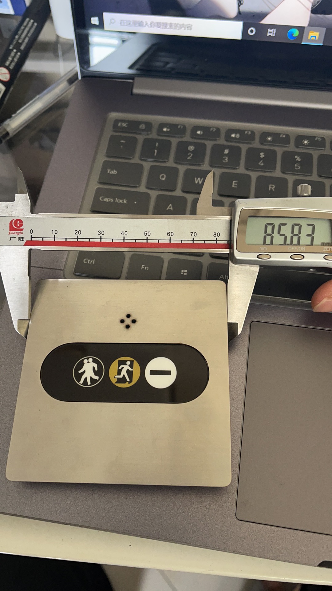
AB门电子互锁/Electronic interlock linkage controller/86外盒指示灯
型号: WX-HS02-86(两门互锁控制器)
型号:wx-HS03-86(三门互锁控制器)
型号:WX-HS04-86(4门互锁控制器)
(可以选配:接入电磁锁,电锁口等电控锁/指示灯选配(可选/不可选))
微电脑电子互锁使用说明书
本系统采用进口芯片,稳定性高、功耗小、响应速度快、无程序错乱、体积小功能齐全。单锁体功耗低于10W,升温低,耐久度高,是净化行业理想配件!
一、工作原理
1、接通电源后,关联的门都保持关闭,系统开始进入正常状态,互锁待机。当其中一扇门被打开之后,另外的门自动闭锁,员工打开门进入气闸室(缓冲间),必须关闭外门,另外的内门才会解锁,如果一扇门打开时间超过20秒,控制器内置的蜂鸣器会发出滴、滴、滴声响,提示将门关闭。(注意:锁安装好之后控制器发出滴、滴声响可能感应锁片上的发射区没有对准锁锁面上的感应区或者门缝较大导致的)
2、当关联的门其中一扇打开时间超过180秒后,另外上锁的门会自动解锁。
3、如果发生突发状况导致停电,电锁会自动解锁,所有门都可打开。
二、安装方法
1、控制盒安装:将控制器固定在气闸室(缓冲间)吊顶上方,用电锁连接线分别与电插锁相连接,接通220V电源即可正常使用。
2、电插锁安装:在门框上方或者侧面的合适位置用圆形开孔器开一个直径30mm的圆孔(电插锁安装孔),找准位置在吊顶上方开孔,将锁线从彩钢板夹层中穿下(类似于在洁净室装插座,需在彩钢板夹层中走暗线),将锁线插头插进电插锁尾部插口,将电插锁锁身全部推入电插锁安装孔,然后根据锁面板上的固定孔钻4.2mm的圆孔用铆钉进行固定。
3、磁感应锁片安装:锁体安装完毕后根据锁面板确定锁片安装位置,锁片安装孔同样是30mm的圆孔,(注意:磁感应锁片安装孔与电插锁安装孔不是正对的,磁感应锁片安装孔的中心位置应该是电插锁安装孔中心向一边移5mm,安装时确定发射区与接收区对准就可判断是往左还是往右偏5mm)
三、注意事项
1、该互锁系统需要配合闭门器或者普通门锁使用,因为当门都关闭时互锁的电插锁都是不上锁的状态,无法使关联门都保持关闭。
2、门缝较大时候请在固定锁体与锁片时垫一些垫片。
3、连接线插入插口时有正反,需要注意方向。
4、电控锁可安装在门侧面或者顶部,请根据实际情况选择合适安装位置。
四、故障排除
1、通电后控制器电源指示灯不亮,检查供电是否有220V。
2、不能正常工作,或者通电后一扇门上锁打不开,检查发射区与感应区是否对准,连接线是否松动,当控制器发出滴、滴的声响时是锁体上的感应区无法感应到发射区所导致。
Microcomputer electronic interlock instruction manual
This system adopts imported chips, high stability, low power consumption, fast response speed, no program disorder, small size and complete functions. The power consumption of a single lock body is less than 10W, the temperature rise is low, and the durability is high. It is an ideal accessory for the purification industry!
1. Working principle
1. After the power is turned on, the associated doors are kept closed, and the system starts to enter the normal state, interlocking standby. When one of the doors is opened, the other doors are automatically locked, and the employee opens the door to enter the airlock room (buffer room). The outer door must be closed before the other inner door will be unlocked. If one door is opened for more than 20 seconds, The built-in buzzer of the controller will make a beep, beep, and beep, prompting to close the door. (Note: After the lock is installed, the controller emits a beeping sound, which may be caused by the transmission area on the lock plate not being aligned with the sensing area on the lock surface or the door gap is large)
2. When one of the associated doors is opened for more than 180 seconds, the other locked door will be automatically unlocked.
3. In the event of an emergency that causes a power outage, the electric lock will be automatically unlocked and all doors can be opened.
2. Installation method
1. Control box installation: Fix the controller on the ceiling of the airlock room (buffer room), connect the electric lock cables to the electric bolt locks, and switch on the 220V power supply for normal use.
2. Electric bolt lock installation: Use a circular hole opener to open a 30mm diameter round hole (electric bolt lock installation hole) at a suitable position above or on the side of the door frame. Pass through the steel plate interlayer (similar to installing a socket in a clean room, you need to run the hidden wire in the color steel plate interlayer), insert the lock wire plug into the socket of the electric bolt lock, and push the electric bolt lock body into the electric bolt lock installation hole , And then drill a 4.2mm round hole according to the fixing hole on the lock panel to fix it with rivets.
3. Magnetic induction lock plate installation: After the lock body is installed, determine the lock plate installation position according to the lock panel. The lock plate installation hole is also a 30mm round hole. (Note: the magnetic induction lock plate installation hole and the electric bolt lock installation hole are not right. , The center position of the mounting hole of the magnetic induction lock plate should be 5mm away from the center of the mounting hole of the electric mortise lock. When installing, make sure that the transmitting area is aligned with the receiving area and you can judge whether it is 5mm to the left or to the right)
Three, matters needing attention
1. The interlocking system needs to be used with door closers or ordinary door locks, because when the doors are closed, the interlocked electric bolt locks are not locked, and the associated doors cannot be kept closed.
2. When the door gap is large, please pad some gaskets when fixing the lock body and the lock plate.
3. When the connecting line is inserted into the socket, there are positive and negative, so you need to pay attention to the direction.
4. The electric control lock can be installed on the side or top of the door, please choose a suitable installation position according to the actual situation.
Four, troubleshooting
1. The controller power indicator does not light up after power on, check whether the power supply is 220V.
2. Cannot work normally, or a door cannot be opened after power on, check whether the launching area is aligned with the sensing area, whether the connection line is loose, when the controller makes a beeping sound, it is the sensing area on the lock body Inability to sense the launch area.
")
")